
If you’re looking to use a hypervisor for analysis and reverse engineering tasks, check out HyperDbg Debugger. It’s a hypervisor-based debugger designed specifically for analyzing, fuzzing, and reversing applications. A free and comprehensive tutorial on hypervisor-based reverse engineering is available at OpenSecurityTraining2’s website (preferred) and YouTube, which demonstrates numerous practical examples on how to utilize hypervisors for reverse engineering.
Introduction
Welcome to the 4th part of the “Hypervisor From Scratch”. This part primarily involves translating guest addresses through Extended Page Table (EPT) and its implementation. We also see how shadow tables work and basic concepts about EPT.
Table of Contents
- Introduction
- Table of Contents
- Overview
- Second Level Address Translation (SLAT)
- Software-assisted paging (Shadow Page Tables)
- Hardware-assisted paging (Extended Page Table)
- Extended Page Table vs. Shadow Page Table
- Detecting Support for EPT, NPT
- EPT Translation
- Implementing Extended Page Table (EPT)
- Accessed and Dirty Flags in EPTP
- 5-Level EPT Translation
- Conclusion
- References
Overview
First of all, make sure to read the earlier parts before reading this topic, as these parts depend on each other. It would help if you also had a basic understanding of the paging mechanism and how page tables work. A good article is here for paging tables.
Most of this topic is derived from Chapter 28 - (VMX SUPPORT FOR ADDRESS TRANSLATION) available at Intel 64 and IA-32 architectures software developer’s manual combined volumes 3.
The full source code of this tutorial is available on GitHub :
[https://github.com/SinaKarvandi/Hypervisor-From-Scratch]
Before starting, I should give my thanks to Petr Beneš, as this part would never have been completed without his help.
Note: This part tends to give you basic information about EPT. The main implementation of EPT for our hypervisor is explained in part 7. In part 7, we used the concept we learned here to implement EPT on an already virtualized system.
Note: Remember that hypervisors change over time because new features are added to the operating systems or new technologies are used. For example, updates to Meltdown & Spectre have made a lot of changes to the hypervisors. So, if you want to use Hypervisor From Scratch in your projects, research, or whatever, you should use the HyperDbg drivers. HyperDbg is actively maintained, stable, and reliable, ensuring you avoid the errors and instability problems that can arise from using older parts of the tutorial series.
Second Level Address Translation (SLAT)
Second Level Address Translation (SLAT) or nested paging is an extended layer in the paging mechanism used to map hardware-based virtualization virtual addresses into the physical memory.
AMD implemented SLAT through the Rapid Virtualization Indexing (RVI) technology known as Nested Page Tables (NPT) since the introduction of its third-generation Opteron processors and microarchitecture code name Barcelona. Intel also implemented SLAT in Intel VT-x technologies since the introduction of microarchitecture code name Nehalem and it’s known as Extended Page Table (EPT) and is used in Core i9, Core i7, Core i5, and Core i3 processors.
ARM processors also have an implementation known as Stage-2 page-tables.
There are two methods for implementing SLAT. The first one is Shadow Page Tables, and the second one is Extended Page Tables.
Software-assisted paging (Shadow Page Tables)
The hypervisor uses Shadow Page Tables to keep track of the state of physical memory in which the guest thinks that it has access to physical memory, but in the real world, the hardware prevents it from accessing hardware memory.
Without this prevention, the guest might control the host, which is not what is intended.
In this case, VMM maintains Shadow Page Tables that map guest virtual pages directly to machine pages.
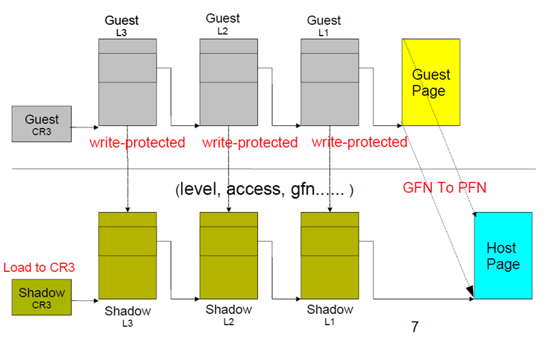
By the way, using Shadow Page Table is not recommended today as it always leads to VMM traps (which result in a vast amount of VM-exits) and losses the performance due to the TLB flush on every switch. Another caveat is that there is a memory overhead due to shadow copying of guest page tables.
Hardware-assisted paging (Extended Page Table)

To reduce the complexity of Shadow Page Tables, avoid the excessive VM-exits, and reduce the number of TLB flushes, EPT implemented a hardware-assisted paging strategy to increase performance.
According to a VMware evaluation paper: “EPT provides performance gains of up to 48% for MMU-intensive benchmarks and up to 600% for MMU-intensive microbenchmarks”.
EPT implemented one more page table hierarchy to map guest virtual address to guest physical address, which is valid in the main memory.
In EPT,
- One page table is maintained by guest OS, which is used to generate the guest’s physical address.
- The other page table is maintained by VMM, which maps the guest’s physical address to the host’s physical address.
So for each memory access operation, EPT MMU directly gets the guest’s physical address from the guest page table and then automatically gets the host’s physical address from the VMM mapping table.
Extended Page Table vs. Shadow Page Table
EPT:
- Walk any requested address
- Appropriate to programs that have a large amount of page table miss when executing
- Less chance to exit VM (less context switch)
- Two-layer EPT
- Means each access needs to walk two tables
- Easier to develop
- Many particular registers
- Hardware helps guest OS to notify the VMM
SPT:
- Only walk when SPT entry miss
- Appropriate to programs that would access only some addresses frequently
- Every access might be intercepted by VMM (many traps)
- One reference
- Fast and convenient when page hit
- Hard to develop
- Two-layer structure
- Complicated reverse map
- Permission emulation
Detecting Support for EPT, NPT
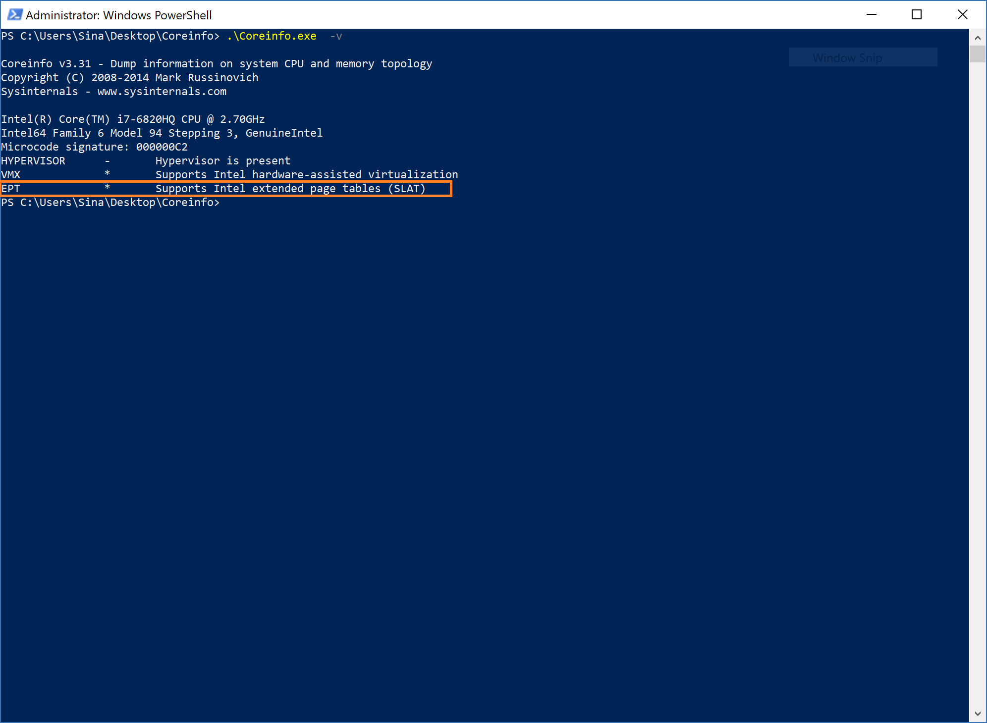
If you want to see whether your system supports EPT on Intel processor or NPT on AMD processor without using assembly (CPUID), you can download coreinfo.exe from SysInternals, then run it. The last line will show you if your processor supports EPT or NPT.
EPT Translation
EPT defines a layer of address translation that augments the translation of linear addresses.
The extended page-table mechanism (EPT) is a feature that can be used to support the virtualization of physical memory. When EPT is in use, certain addresses that would normally be treated as physical addresses (and used to access memory) are instead treated as guest physical addresses. Guest physical addresses are translated by traversing a set of EPT paging structures to produce physical addresses that are used to access memory.
EPT is used when the “enable EPT” VM-execution control is 1. It translates the guest physical addresses used in VMX non-root operation and those used by VM entry for event injection.
EPT translation is exactly like regular paging translation but with some minor differences. In paging, the processor translates a virtual address to a physical address, while in EPT translation, we want to translate a guest’s physical address to a host’s physical address.
If you’re familiar with paging, the 3rd control register (CR3) is the base address of the PML4 table (in an x64 processor or, more generally, it points to the root paging directory). In EPT guest is not aware of EPT translation, so it has CR3 too, but this CR3 is used to convert the guest’s virtual address to the guest’s physical address. Whenever we find our target (the guest’s physical address), the EPT mechanism treats our guest’s physical address like a virtual address and converts it to the host’s physical address. In this mechanism, EPTP is like CR3 but for EPT.
Just think about the above sentence one more time!
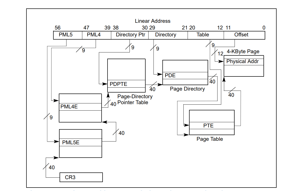
So your target physical address should be divided into four parts. The first 9 bits point to EPT PML4E (note that the PML4 base address is in EPTP). The second 9 bits indicate the EPT PDPT Entry (the base address of PDPT comes from EPT PML4E), the third 9 bits point to EPT PD Entry (the base address of PD comes from EPT PDPTE), and the last 9 bits of the guest physical address point to an entry in EPT PT table (the base address of PT comes from EPT PDE) and now the EPT PT Entry points to the host physical address of the corresponding page.
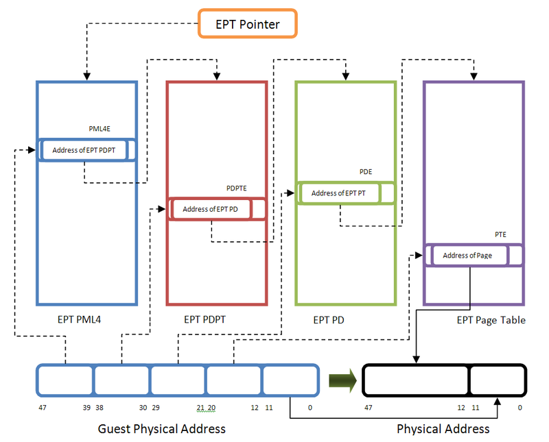
You might ask, as a simple Virtual to Physical Address translation involves accessing four physical addresses, so what happens?
The answer is the processor internally translates all tables’ physical addresses one by one; that’s why paging and accessing memory in a guest software is slower than hardware address translation. The following picture illustrates the operations for a guest’s virtual address to the host’s physical address.
![]()
If you want to think about x86 EPT virtualization, assume, for example, that CR4.PAE = CR4.PSE = 0. The translation of a 32-bit linear address then operates as follows:
- Bits 31:22 of the linear address select an entry in the guest page directory located at the guest physical address in CR3. The guest’s physical address of the guest page-directory entry (PDE) is translated through EPT to determine the guest PDE’s physical address.
- Bits 21:12 of the linear address select an entry in the guest page table located at the guest’s physical address in the guest PDE. The guest physical address of the guest page-table entry (PTE) is translated through EPT to determine the guest PTE’s physical address.
- Bits 11:0 of the linear address is the offset in the page frame located at the guest’s physical address in the guest PTE. The guest’s physical address determined by this offset is translated through EPT to select the physical address to which the original linear address translates.
Note that PAE stands for Physical Address Extension, which is a memory management feature for the x86 architecture that extends the address space, and PSE stands for Page Size Extension that refers to a feature of x86 processors that allows for pages larger than the standard 4 KiB size.
In addition to translating a guest’s physical address to a host’s physical address, EPT specifies the privileges that software is allowed when accessing the address. Attempts at disallowed accesses are called EPT violations and cause VM-exits.
Remember that an address will not translate through EPT when there is no read/write access.
Implementing Extended Page Table (EPT)
Now that we know some basics, let’s implement what we’ve learned before. Based on the Intel manual, we should write (VMWRITE) EPTP or Extended-Page-Table Pointer to the VMCS. The EPTP structure is described below.
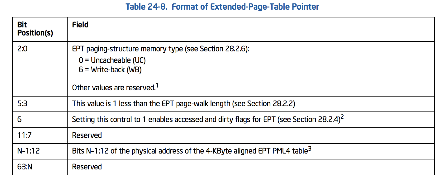
The above tables can be described using the following structure:
1
2
3
4
5
6
7
8
9
10
11
12
// See Table 24-8. Format of Extended-Page-Table Pointer
typedef union _EPTP {
    ULONG64 All;
    struct {
        UINT64 MemoryType : 3; // bit 2:0 (0 = Uncacheable (UC) - 6 = Write - back(WB))
        UINT64 PageWalkLength : 3; // bit 5:3 (This value is 1 less than the EPT page-walk length)
        UINT64 DirtyAndAceessEnabled : 1; // bit 6  (Setting this control to 1 enables accessed and dirty flags for EPT)
        UINT64 Reserved1 : 5; // bit 11:7
        UINT64 PML4Address : 36;
        UINT64 Reserved2 : 16;
    }Fields;
}EPTP, *PEPTP;
Like the regular paging mechanism, each entry in all EPT tables is 64-bit long. EPT PML4E, EPT PDPTE, and EPT PD are the same, but EPT PTE has some minor differences.
An EPT entry is something like this:

Ok, Now we should implement tables; the first table is PML4. The following table shows the format of an EPT PML4 Entry (PML4E).
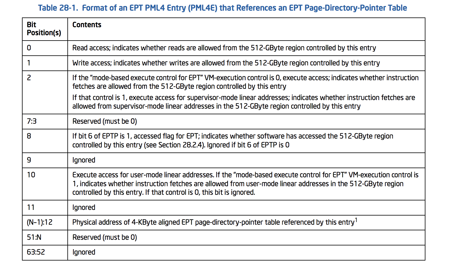
PML4E is a structure like this :
1
2
3
4
5
6
7
8
9
10
11
12
13
14
15
16
17
// See Table 28-1.
typedef union _EPT_PML4E {
    ULONG64 All;
    struct {
        UINT64 Read : 1; // bit 0
        UINT64 Write : 1; // bit 1
        UINT64 Execute : 1; // bit 2
        UINT64 Reserved1 : 5; // bit 7:3 (Must be Zero)
        UINT64 Accessed : 1; // bit 8
        UINT64 Ignored1 : 1; // bit 9
        UINT64 ExecuteForUserMode : 1; // bit 10
        UINT64 Ignored2 : 1; // bit 11
        UINT64 PhysicalAddress : 36; // bit (N-1):12 or Page-Frame-Number
        UINT64 Reserved2 : 4; // bit 51:N
        UINT64 Ignored3 : 12; // bit 63:52
    }Fields;
}EPT_PML4E, *PEPT_PML4E;
As long as we use 4-level paging, the second table is EPT Page-Directory-Pointer-Table (PDTP). The following picture illustrates the format of PDPTE:
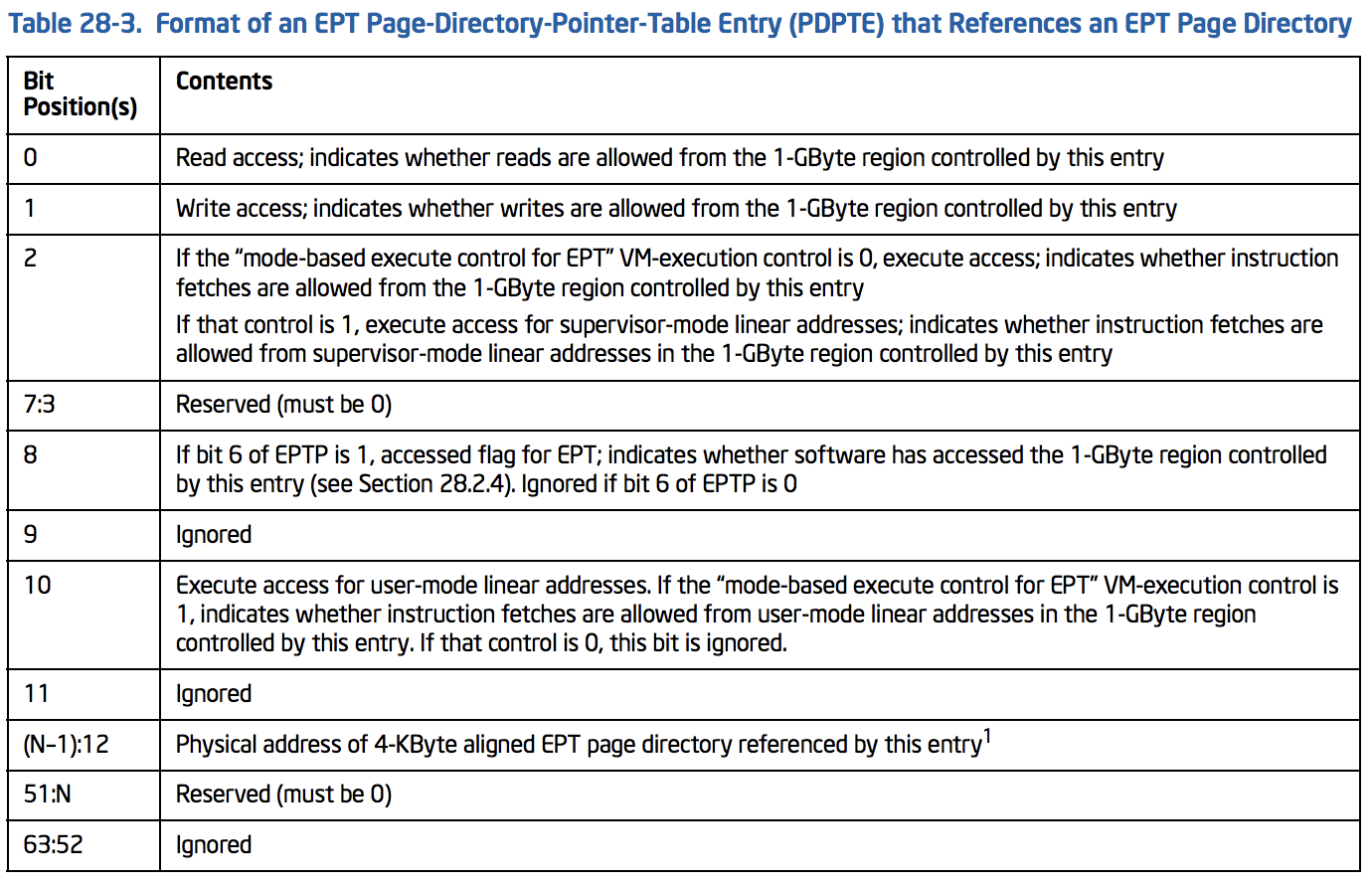
PDPTE’s structure is like this:
1
2
3
4
5
6
7
8
9
10
11
12
13
14
15
16
17
// See Table 28-3
typedef union _EPT_PDPTE {
    ULONG64 All;
    struct {
        UINT64 Read : 1; // bit 0
        UINT64 Write : 1; // bit 1
        UINT64 Execute : 1; // bit 2
        UINT64 Reserved1 : 5; // bit 7:3 (Must be Zero)
        UINT64 Accessed : 1; // bit 8
        UINT64 Ignored1 : 1; // bit 9
        UINT64 ExecuteForUserMode : 1; // bit 10
        UINT64 Ignored2 : 1; // bit 11
        UINT64 PhysicalAddress : 36; // bit (N-1):12 or Page-Frame-Number
        UINT64 Reserved2 : 4; // bit 51:N
        UINT64 Ignored3 : 12; // bit 63:52
    }Fields;
}EPT_PDPTE, *PEPT_PDPTE;
For the third table of paging, we should implement an EPT Page-Directory Entry (PDE) as described below:
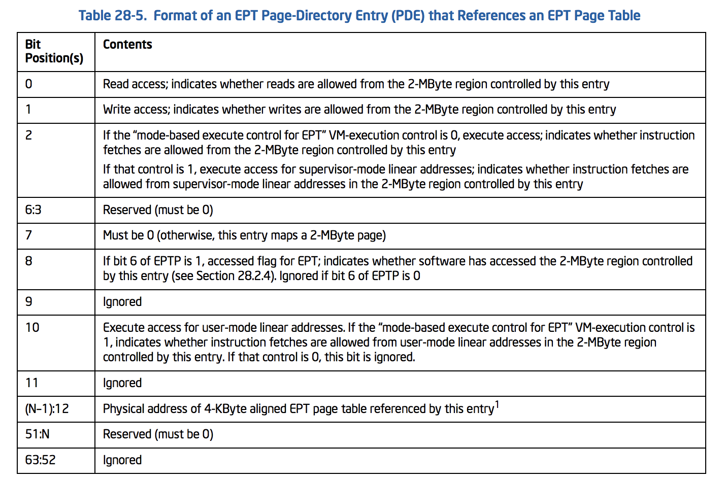
PDE’s structure:
1
2
3
4
5
6
7
8
9
10
11
12
13
14
15
16
17
// See Table 28-5
typedef union _EPT_PDE {
    ULONG64 All;
    struct {
        UINT64 Read : 1; // bit 0
        UINT64 Write : 1; // bit 1
        UINT64 Execute : 1; // bit 2
        UINT64 Reserved1 : 5; // bit 7:3 (Must be Zero)
        UINT64 Accessed : 1; // bit 8
        UINT64 Ignored1 : 1; // bit 9
        UINT64 ExecuteForUserMode : 1; // bit 10
        UINT64 Ignored2 : 1; // bit 11
        UINT64 PhysicalAddress : 36; // bit (N-1):12 or Page-Frame-Number
        UINT64 Reserved2 : 4; // bit 51:N
        UINT64 Ignored3 : 12; // bit 63:52
    }Fields;
}EPT_PDE, *PEPT_PDE;
The last page is EPT which is described below.
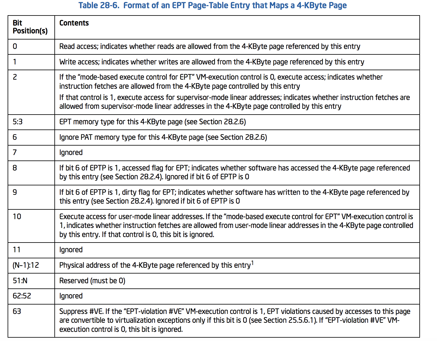
PTE will be :
Note that we have EPTMemoryType, IgnorePAT, DirtyFlag, and SuppressVE in addition to the above pages.
1
2
3
4
5
6
7
8
9
10
11
12
13
14
15
16
17
18
19
20
// See Table 28-6
typedef union _EPT_PTE {
    ULONG64 All;
    struct {
        UINT64 Read : 1; // bit 0
        UINT64 Write : 1; // bit 1
        UINT64 Execute : 1; // bit 2
        UINT64 EPTMemoryType : 3; // bit 5:3 (EPT Memory type)
        UINT64 IgnorePAT : 1; // bit 6
        UINT64 Ignored1 : 1; // bit 7
        UINT64 AccessedFlag : 1; // bit 8
        UINT64 DirtyFlag : 1; // bit 9
        UINT64 ExecuteForUserMode : 1; // bit 10
        UINT64 Ignored2 : 1; // bit 11
        UINT64 PhysicalAddress : 36; // bit (N-1):12 or Page-Frame-Number
        UINT64 Reserved : 4; // bit 51:N
        UINT64 Ignored3 : 11; // bit 62:52
        UINT64 SuppressVE : 1; // bit 63
    }Fields;
}EPT_PTE, *PEPT_PTE;
There are other types of implementing page walks (2 or 3 level paging), and if you set the 7th bit of PDPTE (Maps 1 GB) or the 7th bit of PDE (Maps 2 MB) so instead of implementing 4-level paging (like what we want to do for the rest of the topic) we set those bits but keep in mind that the corresponding tables are different. These tables are described in (Table 28-4. Format of an EPT Page-Directory Entry (PDE) that Maps a 2-MByte Page) and (Table 28-2. Format of an EPT Page-Directory-Pointer-Table Entry (PDPTE) that Maps a 1-GByte Page). SimpleVisor is an example of this implementation.
An important note is almost all the above structures have a 36-bit Physical Address which means our hypervisor supports only 4-level paging. It is because every page table (and every EPT Page Table) consists of 512 entries which means you need 9 bits to select an entry, and as long as we have 4 level tables, we can’t use more than 36 (4 * 9) bits. Another method with a wider address range is not implemented in all major OS like Windows or Linux. I’ll describe EPT PML5E briefly later in this topic, but we don’t implement it in our hypervisor as it’s not widespread yet!
By the way, N is the physical address width supported by the processor. CPUID with 80000008H in EAX gives you the supported width in EAX bits 7:0.
Let’s see the rest of the code. The following code is the InitializeEptp function which is responsible for allocating and mapping EPTP.
Note that the PAGED_CODE() macro ensures that the calling thread runs at an IRQL low enough to permit paging.
1
2
3
4
5
UINT64
InitializeEptp()
{
    PAGED_CODE();
        ...
First of all, allocate EPTP and put zeros on it.
1
2
3
4
5
6
7
8
9
10
    //
    // Allocate EPTP
    //
    PEPTP EPTPointer = ExAllocatePoolWithTag(NonPagedPool, PAGE_SIZE, POOLTAG);

    if (!EPTPointer)
    {
        return NULL;
    }
    RtlZeroMemory(EPTPointer, PAGE_SIZE);
Now, we need a blank page for our EPT PML4 Table.
1
2
3
4
5
6
7
8
9
10
    //
    //  Allocate EPT PML4
    //
    PEPT_PML4E EptPml4 = ExAllocatePoolWithTag(NonPagedPool, PAGE_SIZE, POOLTAG);
    if (!EptPml4)
    {
        ExFreePoolWithTag(EPTPointer, POOLTAG);
        return NULL;
    }
    RtlZeroMemory(EptPml4, PAGE_SIZE);
And another empty page for PDPT.
1
2
3
4
5
6
7
8
9
10
11
    //
    //  Allocate EPT Page-Directory-Pointer-Table
    //
    PEPT_PDPTE EptPdpt = ExAllocatePoolWithTag(NonPagedPool, PAGE_SIZE, POOLTAG);
    if (!EptPdpt)
    {
        ExFreePoolWithTag(EptPml4, POOLTAG);
        ExFreePoolWithTag(EPTPointer, POOLTAG);
        return NULL;
    }
    RtlZeroMemory(EptPdpt, PAGE_SIZE);
Of course, it’s true about Page Directory Table.
1
2
3
4
5
6
7
8
9
10
11
12
13
    //
    //  Allocate EPT Page-Directory
    //
    PEPT_PDE EptPd = ExAllocatePoolWithTag(NonPagedPool, PAGE_SIZE, POOLTAG);

    if (!EptPd)
    {
        ExFreePoolWithTag(EptPdpt, POOLTAG);
        ExFreePoolWithTag(EptPml4, POOLTAG);
        ExFreePoolWithTag(EPTPointer, POOLTAG);
        return NULL;
    }
    RtlZeroMemory(EptPd, PAGE_SIZE);
The last table is a blank page for EPT Page Table.
1
2
3
4
5
6
7
8
9
10
11
12
13
14
    //
    //  Allocate EPT Page-Table
    //
    PEPT_PTE EptPt = ExAllocatePoolWithTag(NonPagedPool, PAGE_SIZE, POOLTAG);

    if (!EptPt)
    {
        ExFreePoolWithTag(EptPd, POOLTAG);
        ExFreePoolWithTag(EptPdpt, POOLTAG);
        ExFreePoolWithTag(EptPml4, POOLTAG);
        ExFreePoolWithTag(EPTPointer, POOLTAG);
        return NULL;
    }
    RtlZeroMemory(EptPt, PAGE_SIZE);
Now that we have all of our pages available, let’s allocate two pages (2*4096) continuously because we need one of the pages for our RIP register to start and one page for our stack (RSP register). After that, we need two EPT Page Table Entries (PTEs) with permission to execute, read, and write. The physical address should be divided by 4096 (PAGE_SIZE) because if we dived a hex number by 4096 (0x1000), 12 digits from the right (which are zeros) would disappear, and these 12 digits are for choosing between 4096 bytes.
By the way, we let stack be executable. That’s because, in a regular VM, we should put RWX on all pages. After all, it’s the responsibility of internal page tables to set or clear NX bit. We need to change them from EPT tables for special purposes (e.g., intercepting instruction fetch for a special page). Changing from EPT tables will lead to EPT-Violation; this way, we can intercept these events.
The actual need is two pages, but we need to build page tables inside our guest software; thus, we allocate up to 10 pages.
I’ll explain about intercepting pages from EPT later in this series.
1
2
3
4
5
6
7
8
9
10
11
12
13
14
15
16
17
18
19
20
21
    //
    // Setup PT by allocating two pages Continuously
    // We allocate two pages because we need 1 page for our RIP to start and 1 page for RSP 1 + 1 = 2
    //
    const int PagesToAllocate = 10;
    UINT64    GuestMemory     = ExAllocatePoolWithTag(NonPagedPool, PagesToAllocate * PAGE_SIZE, POOLTAG);
    RtlZeroMemory(GuestMemory, PagesToAllocate * PAGE_SIZE);

    for (size_t i = 0; i < PagesToAllocate; i++)
    {
        EptPt[i].Fields.AccessedFlag       = 0;
        EptPt[i].Fields.DirtyFlag          = 0;
        EptPt[i].Fields.EPTMemoryType      = 6;
        EptPt[i].Fields.Execute            = 1;
        EptPt[i].Fields.ExecuteForUserMode = 0;
        EptPt[i].Fields.IgnorePAT          = 0;
        EptPt[i].Fields.PhysicalAddress    = (VirtualToPhysicalAddress(GuestMemory + (i * PAGE_SIZE)) / PAGE_SIZE);
        EptPt[i].Fields.Read               = 1;
        EptPt[i].Fields.SuppressVE         = 0;
        EptPt[i].Fields.Write              = 1;
    }
Note: EPTMemoryType can be either 0 (for uncached memory) or 6 (writeback) memory, and as we want our memory to be cacheable, so put 6 on it.
The next table is PDE. PDE should point to the PTE base address, so we just put the address of the first entry from the EPT PTE as the physical address for Page Directory Entry.
1
2
3
4
5
6
7
8
9
10
11
12
13
14
    //
    // Setting up PDE
    //
    EptPd->Fields.Accessed           = 0;
    EptPd->Fields.Execute            = 1;
    EptPd->Fields.ExecuteForUserMode = 0;
    EptPd->Fields.Ignored1           = 0;
    EptPd->Fields.Ignored2           = 0;
    EptPd->Fields.Ignored3           = 0;
    EptPd->Fields.PhysicalAddress    = (VirtualToPhysicalAddress(EptPt) / PAGE_SIZE);
    EptPd->Fields.Read               = 1;
    EptPd->Fields.Reserved1          = 0;
    EptPd->Fields.Reserved2          = 0;
    EptPd->Fields.Write              = 1;
The next step is mapping PDPT. PDPT Entry should point to the first entry of Page-Directory.
1
2
3
4
5
6
7
8
9
10
11
12
13
14
    //
    // Setting up PDPTE
    //
    EptPdpt->Fields.Accessed           = 0;
    EptPdpt->Fields.Execute            = 1;
    EptPdpt->Fields.ExecuteForUserMode = 0;
    EptPdpt->Fields.Ignored1           = 0;
    EptPdpt->Fields.Ignored2           = 0;
    EptPdpt->Fields.Ignored3           = 0;
    EptPdpt->Fields.PhysicalAddress    = (VirtualToPhysicalAddress(EptPd) / PAGE_SIZE);
    EptPdpt->Fields.Read               = 1;
    EptPdpt->Fields.Reserved1          = 0;
    EptPdpt->Fields.Reserved2          = 0;
    EptPdpt->Fields.Write              = 1;
The last step is configuring PML4E, which points to the first entry of the PTPT.
1
2
3
4
5
6
7
8
9
10
11
12
13
14
    //
    // Setting up PML4E
    //
    EptPml4->Fields.Accessed           = 0;
    EptPml4->Fields.Execute            = 1;
    EptPml4->Fields.ExecuteForUserMode = 0;
    EptPml4->Fields.Ignored1           = 0;
    EptPml4->Fields.Ignored2           = 0;
    EptPml4->Fields.Ignored3           = 0;
    EptPml4->Fields.PhysicalAddress    = (VirtualToPhysicalAddress(EptPdpt) / PAGE_SIZE);
    EptPml4->Fields.Read               = 1;
    EptPml4->Fields.Reserved1          = 0;
    EptPml4->Fields.Reserved2          = 0;
    EptPml4->Fields.Write              = 1;
We’ve almost done! Just set up the EPTP for our VMCS by putting 0x6 as the memory type (which is writeback), and we walk four times, so the page walk length is 4-1=3, and the PML4 address is the physical address of the first entry in the PML4 table.
I’ll explain the DirtyAndAcessEnabled field later in this topic.
1
2
3
4
5
6
7
8
9
    //
    // Setting up EPTP
    //
    EPTPointer->Fields.DirtyAndAceessEnabled = 1;
    EPTPointer->Fields.MemoryType            = 6; // 6 = Write-back (WB)
    EPTPointer->Fields.PageWalkLength        = 3; // 4 (tables walked) - 1 = 3
    EPTPointer->Fields.PML4Address           = (VirtualToPhysicalAddress(EptPml4) / PAGE_SIZE);
    EPTPointer->Fields.Reserved1             = 0;
    EPTPointer->Fields.Reserved2             = 0;
And the last step.
1
2
    DbgPrint("[*] Extended Page Table Pointer allocated at %llx", EPTPointer);
    return EPTPointer;
All the above page tables should be aligned to 4KByte boundaries, but as long as we allocate >= PAGE_SIZE (One PFN record) so it’s automatically 4kb-aligned.
Our implementation consists of 4 tables; therefore, the full layout is like this:

Accessed and Dirty Flags in EPTP
In EPTP, we’ll decide whether enable accessed and dirty flags for EPT or not using the 6th bit of the extended-page-table pointer (EPTP). Setting this flag causes processor accesses to guest paging structure entries to be treated as writes.
For any EPT paging-structure entry that is used during guest-physical-address translation, bit 8 is the accessed flag. For an EPT paging-structure entry that maps a page (as opposed to referencing another EPT paging structure), bit 9 is the dirty flag.
Whenever the processor uses an EPT paging-structure entry as part of the guest-physical-address translation, it sets the accessed flag in that entry (if it is not already set).
Whenever there is a write to a guest physical address, the processor sets the dirty flag (if it is not already set) in the EPT paging-structure entry that identifies the final physical address for the guest’s physical address (either an EPT PTE or an EPT paging-structure entry in which bit 7 is 1).
These flags are “sticky”, meaning that, once set, the processor does not clear them; only software can clear them.
5-Level EPT Translation
Intel suggests a new table in translation hierarchy, called PML5 which extends the EPT into a 5-layer table, and guest operating systems can use up to 57 bits for the virtual addresses, while the classic 4-level EPT is limited to translating 48-bit guest physical addresses. None of the modern OSs use this feature yet.
PML5 is also applied to both EPT and regular paging mechanisms.
Translation begins by identifying a 4-KByte naturally aligned EPT PML5 table. It is located at the physical address specified in bits 51:12 of EPTP. An EPT PML5 table comprises 512 64-bit entries (EPT PML5Es). An EPT PML5E is selected using the physical address defined as follows.
- Bits 63:52 are all 0.
- Bits 51:12 are from EPTP.
- Bits 11:3 are bits 56:48 of the guest physical address.
- Bits 2:0 are all 0.
- Because an EPT PML5E is identified using bits 56:48 of the guest’s physical address, it controls access to a 256-TByte region of the linear address space.
The only difference is we should put PML5 physical address instead of the PML4 address in EPTP.
For more information about 5-layer paging, take a look at this Intel documentation.
Conclusion
In this part, we see how to initialize the Extended Page Table (EPT) and map the guest’s physical address to the host’s physical address; then, we build the EPTP based on the allocated addresses.
The future part would be about building the VMCS and implementing other VMX instructions and functionalities.
The fifth part is also available here.
Have a good time!

References
[1] Vol 3C - 28.2 THE EXTENDED PAGE TABLE MECHANISM (EPT) (https://software.intel.com/en-us/articles/intel-sdm)
[2] Performance Evaluation of Intel EPT Hardware Assist (https://www.vmware.com/pdf/Perf_ESX_Intel-EPT-eval.pdf)
[3] Second Level Address Translation (https://en.wikipedia.org/wiki/Second_Level_Address_Translation)
[4] Memory Virtualization (http://www.cs.nthu.edu.tw/~ychung/slides/Virtualization/VM-Lecture-2-2-SystemVirtualizationMemory.pptx)
[5] Best Practices for Paravirtualization Enhancements from Intel® Virtualization Technology: EPT and VT-d (https://software.intel.com/en-us/articles/best-practices-for-paravirtualization-enhancements-from-intel-virtualization-technology-ept-and-vt-d)
[6] 5-Level Paging and 5-Level EPT (https://software.intel.com/sites/default/files/managed/2b/80/5-level_paging_white_paper.pdf)
[7] Xen Summit November 2007 - Jun Nakajima (http://www-archive.xenproject.org/files/xensummit_fall07/12_JunNakajima.pdf)
[8] gipervizor against rutkitov: as it works (http://developers-club.com/posts/133906/)
[9] Intel SGX Explained (https://www.semanticscholar.org/paper/Intel-SGX-Explained-Costan-Devadas/2d7f3f4ca3fbb15ae04533456e5031e0d0dc845a)
[10] Intel VT-x (https://github.com/tnballo/notebook/wiki/Intel-VTx)
[11] Introduction to IA-32e hardware paging (https://www.triplefault.io/2017/07/introduction-to-ia-32e-hardware-paging.html)
Comments powered by Disqus.