
If you’re looking to use a hypervisor for analysis and reverse engineering tasks, check out HyperDbg Debugger. It’s a hypervisor-based debugger designed specifically for analyzing, fuzzing, and reversing applications. A free and comprehensive tutorial on hypervisor-based reverse engineering is available at OpenSecurityTraining2’s website (preferred) and YouTube, which demonstrates numerous practical examples on how to utilize hypervisors for reverse engineering.
Introduction
This is the third part of the tutorial “Hypervisor From Scratch”. In this part, we’ll continue our journey toward learning hypervisors and how to start creating our custom VMM. In the previous part, we learned how to make WDK drivers that handle user-mode requests and enable the VMX bit in our processor. In this part, we extend our driver and add VMX functionalities to our VMM. At last, we use different VT-x instructions in the VMM.
Table of Contents
- Introduction
- Table of Contents
- Overview
- Interacting with the driver from user-mode
- Buffer Descriptions for I/O Control Codes
- METHOD_BUFFERED
- METHOD_IN_DIRECT and METHOD_OUT_DIRECT
- METHOD_NIETHER
- IOCTL Structure
- IOCTL Dispatcher
- Per Processor Configuration
- Setting Affinity
- Converting physical and virtual addresses
- Check VMX support in the kernel
- VMXON Region
- Allocating VMXON Region
- Virtual-Machine Control Data Structures (VMCS)
- Initializing VMCS Region
- VMXOFF Instruction
- Testing VMM
- Conclusion
- References
Overview
In this part, we demonstrate how to interact with VMM from Windows user-mode (IOCTL Dispatcher), then we solve the problems with the affinity and running code in a particular core. Finally, we get familiar with initializing VMXON Regions and VMCS Regions, then we load our hypervisor into each core and implement our custom functions to work with hypervisor instructions and many more things related to Virtual-Machine Control Data Structures (VMCS).
Some of the implementations are derived from HyperBone (Minimalistic VT-X hypervisor with hooks), HyperPlatform by Satoshi Tanda and hvpp which is amazing work by my friend Petr Beneš.
The full source code of this tutorial is available on :
[https://github.com/SinaKarvandi/Hypervisor-From-Scratch]
Interacting with the driver from user-mode
The most important function for us in IRP MJ functions is DrvIoctlDispatcher or (IRP_MJ_DEVICE_CONTROL) Major Function, and that’s because this function can be called from user-mode with a particular IOCTL number, which means we can have a special code in our driver and implement a unique functionality corresponding this code, then by knowing the code (from user-mode) we can ask our driver to perform the request, so this way we can request a certain functionality from the kernel.
Buffer Descriptions for I/O Control Codes
As explained above, IOCTL codes request a certain functionality from the kernel-mode. It’s clear that in most cases, we need to transfer a buffer (structure) to the kernel, which shows different details about our request. Thus, we need to copy the buffer from the user-mode and pass it to the kernel-mode routines.
There are several methods in which Windows copies the buffer of the user-mode codes to the kernel for dispatching IOCTs.
- METHOD_BUFFERED
- METHOD_IN_DIRECT
- METHOD_OUT_DIRECT
- METHOD_NIETHER
The difference is where buffers transfer between user-mode and kernel-mode. Let’s see each of them in detail.
METHOD_BUFFERED
For METHOD_BUFFERED, the pointer to the user-mode buffer is available at Irp->AssociatedIrp.SystemBuffer, and we can put the output buffer to the same address (Irp->AssociatedIrp.SystemBuffer).
This method is typically used for transferring small amounts of data per request. Most I/O control codes for device and intermediate drivers use this type as Windows copies the user-mode buffer to the kernel-mode and the kernel-mode buffer to the user-mode.
METHOD_IN_DIRECT and METHOD_OUT_DIRECT
For these methods, the pointer to the user-mode buffer is available at Irp->AssociatedIrp.SystemBuffer.
This type is generally used for reading or writing large amounts of data that must be transferred fast as it won’t copy the data and instead shares the pages.
The METHOD_IN_DIRECT is specified if the caller pass data to the driver, and the METHOD_OUT_DIRECT is selected if the caller will receive data from the driver.
METHOD_NIETHER
The input buffer address is specified by Parameters.DeviceIoControl.Type3InputBuffer in the driver’s IO_STACK_LOCATION structure, and the output buffer(to the user-mode) is specified by Irp->UserBuffer.
This method is neither buffered nor direct I/O. The I/O manager does not provide any system buffers, and the IRP provides the user-mode virtual addresses of the input and output buffers without validating or mapping them.
IOCTL Structure
We should specify all of the above transferring types into the following structure.
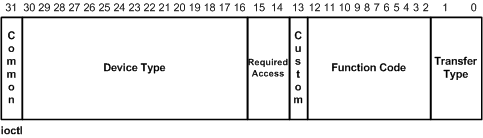
There is a convention for defining IOCTLs as mentioned here. The IOCTL is a 32-bit number. The first two low bits represent the “transfer type”, which can be METHOD_OUT_DIRECT, METHOD_IN_DIRECT, METHOD_BUFFERED, or METHOD_NEITHER.
The next set of bits from 2 to 13 define the “Function Code”. The high bit is referred to as the “custom bit”. This is used to determine user-defined IOCTLs versus system defined. This means that function codes 0x800 and greater are customs defined for Windows Messages.
The next two bits define the access required to issue the IOCTL. This is how the I/O Manager can reject IOCTL requests if the handle has not been opened with the correct access. The access types are such as FILE_READ_DATA, FILE_WRITE_DATA, etc.
The last bits represent the device type the IOCTLs are written for. The high bit again represents user-defined values.
We can use the following defined macro to create our IOCTL code.
1
#define IOCTL_Device_Function CTL_CODE(DeviceType, Function, Method, Access)
For example, the following IOCTL code can be defined.
1
2
#define IOCTL_TEST \
    CTL_CODE(FILE_DEVICE_UNKNOWN, 0x801, METHOD_BUFFERED, FILE_ANY_ACCESS)
IOCTL Dispatcher
Now let’s implement our functions for dispatching IOCTL codes.
Note that the PAGED_CODE() macro ensures that the calling thread runs at an IRQL low enough to permit paging, this macro is used to ensure that paging is enabled, for example, the current execution is not at DISPATCH_LEVEL. Don’t worry; we’ll discuss IRQL in detail in the future parts.
The next step is to check the input buffer and the output buffer’s length. We’ll check it because we need to ensure that the user provides a buffer for the kernel and expects a buffer to be received. The following code gets the input and output buffer length from the IO_STACK_LOCATION.
1
2
3
4
5
6
7
8
9
    IrpStack     = IoGetCurrentIrpStackLocation(Irp);
    InBufLength  = IrpStack->Parameters.DeviceIoControl.InputBufferLength;
    OutBufLength = IrpStack->Parameters.DeviceIoControl.OutputBufferLength;

    if (!InBufLength || OutBufLength < DataLen)
    {
        NtStatus = STATUS_INVALID_PARAMETER;
        goto End;
    }
Then we have to use the switch-case through the IOCTL code.
1
2
3
4
5
6
7
8
9
10
11
12
13
14
15
16
17
18
19
20
21
22
23
24
25
26
27
28
29
30
31
32
33
34
35
36
  switch (IrpStack->Parameters.DeviceIoControl.IoControlCode)
    {
    case IOCTL_SIOCTL_METHOD_BUFFERED:

        ...

        break;

    case IOCTL_SIOCTL_METHOD_NEITHER:

        ...

        break;

    case IOCTL_SIOCTL_METHOD_IN_DIRECT:

        ...

        break;

    case IOCTL_SIOCTL_METHOD_OUT_DIRECT:

        ...

        break;

    default:

        //
        // The specified I/O control code is unrecognized by this driver.
        //
        NtStatus = STATUS_INVALID_DEVICE_REQUEST;
        DbgPrint("ERROR: unrecognized IOCTL %x\n",
                 IrpStack->Parameters.DeviceIoControl.IoControlCode);
        break;
    }
The PrintIrpInfo is like this :
1
2
3
4
5
6
7
8
9
10
11
12
13
14
15
16
17
18
VOID PrintIrpInfo(PIRP Irp)
{
    PIO_STACK_LOCATION  IrpStack;
    IrpStack = IoGetCurrentIrpStackLocation(Irp);

    PAGED_CODE();

    DbgPrint("\tIrp->AssociatedIrp.SystemBuffer = 0x%p\n",
        Irp->AssociatedIrp.SystemBuffer);
    DbgPrint("\tIrp->UserBuffer = 0x%p\n", Irp->UserBuffer);
    DbgPrint("\tIrpStack->Parameters.DeviceIoControl.Type3InputBuffer = 0x%p\n",
        IrpStack->Parameters.DeviceIoControl.Type3InputBuffer);
    DbgPrint("\tIrpStack->Parameters.DeviceIoControl.InputBufferLength = %d\n",
        IrpStack->Parameters.DeviceIoControl.InputBufferLength);
    DbgPrint("\tIrpStack->Parameters.DeviceIoControl.OutputBufferLength = %d\n",
        IrpStack->Parameters.DeviceIoControl.OutputBufferLength);
    return;
}
If you remember from the previous part where we created a handle (HANDLE) using CreateFile, now we can use the DeviceIoControl with the previous handle and call DrvIoctlDispatcher or (IRP_MJ_DEVICE_CONTROL) along with our provided buffer in the kernel.
1
2
3
4
5
6
7
8
9
10
11
12
13
14
15
16
17
18
19
20
21
22
23
24
25
26
27
28
29
    char  OutputBuffer[1000];
    char  InputBuffer[1000];
    ULONG BytesReturned;
    BOOL  Result;

    //
    // Performing METHOD_BUFFERED
    //
    StringCbCopy(InputBuffer, sizeof(InputBuffer), "This String is from User Application; using METHOD_BUFFERED");

    printf("\nCalling DeviceIoControl METHOD_BUFFERED:\n");

    memset(OutputBuffer, 0, sizeof(OutputBuffer));

    Result = DeviceIoControl(Handle,
                             (DWORD)IOCTL_SIOCTL_METHOD_BUFFERED,
                             &InputBuffer,
                             (DWORD)strlen(InputBuffer) + 1,
                             &OutputBuffer,
                             sizeof(OutputBuffer),
                             &BytesReturned,
                             NULL);

    if (!Result)
    {
        printf("Error in DeviceIoControl : %d", GetLastError());
        return false;
    }
    printf("    OutBuffer (%d): %s\n", BytesReturned, OutputBuffer);
For further reading, there is an old, yet great topic here which describes the different types of IOCTL dispatching.
We’re done with WDK basics! It’s time to see how we can use Windows to build our VMM.

Per Processor Configuration
Affinity to a special logical processor is one of the main considerations when working with the hypervisor.
In my Intel Core i7 6820HQ, I have four physical cores, and each core can run two threads simultaneously (due to the hyper-threading); thus, we have eight logical processors and, of course, eight sets of all the registers (including general purpose registers and MSR registers) and more importantly, eight sets of VMCSs and VMXON Regions, etc. so we should configure our VMM to work on eight logical processors.
Setting Affinity
To get the count of logical processors, we can use KeQueryActiveProcessorCount(0). Then we should pass a KAFFINITY mask to the KeSetSystemAffinityThread, which sets the system affinity of the current thread.
KAFFINITY mask can be configured using a simple power function:
1
2
3
4
5
6
7
8
9
10
11
12
13
14
15
16
17
18
19
20
int
MathPower(int Base, int Exponent)
{
    int Result = 1;
    for (;;)
    {
        if (Exponent & 1)
        {
            Result *= Base;
        }

        Exponent >>= 1;
        if (!Exponent)
        {
            break;
        }
        Base *= Base;
    }
    return Result;
}
After that, we should use the following code to change the affinity of the processor and run our code in all the logical cores separately:
1
2
3
4
5
6
7
8
9
10
11
    KAFFINITY AffinityMask;
    for (size_t i = 0; i < KeQueryActiveProcessors(); i++)
    {
        AffinityMask = MathPower(2, i);
        KeSetSystemAffinityThread(AffinityMask);

        DbgPrint("=====================================================");
        DbgPrint("Current thread is executing in %d th logical processor.", i);

        // run code here
    }
This way, we can run our codes in the different logical cores. Now, let’s see other essential functionalities we need for our hypervisor.
Converting physical and virtual addresses
VMXON Regions and VMCS Regions (see below) use the physical address as the operand to VMXON and VMPTRLD instructions, so we should create functions to convert Virtual Address to Physical address:
1
2
3
4
5
UINT64
VirtualToPhysicalAddress(void * Va)
{
    return MmGetPhysicalAddress(Va).QuadPart;
}
And as long as we can’t directly use physical addresses for our modifications in protected-mode, we have to convert Physical addresses to Virtual addresses too.
1
2
3
4
5
6
7
8
UINT64
PhysicalToVirtualAddress(UINT64 Pa)
{
    PHYSICAL_ADDRESS PhysicalAddr;
    PhysicalAddr.QuadPart = Pa;

    return MmGetVirtualForPhysical(PhysicalAddr);
}
Check VMX support in the kernel
In the previous part, we query about the presence of hypervisor from user-mode, but we should also consider checking about hypervisor from kernel-mode too. This reduces the possibility of getting kernel errors in the future, or there might be something that disables the hypervisor using the lock bit. By the way, the following code checks IA32_FEATURE_CONTROL MSR (MSR address 3AH) to see if the lock bit is set or not.
1
2
3
4
5
6
7
8
9
10
11
12
13
14
15
16
17
18
19
20
21
22
23
24
25
26
27
28
29
30
31
32
BOOLEAN
IsVmxSupported()
{
    CPUID Data = {0};

    //
    // Check for the VMX bit
    //
    __cpuid((int *)&Data, 1);
    if ((Data.ecx & (1 << 5)) == 0)
        return FALSE;

    IA32_FEATURE_CONTROL_MSR Control = {0};
    Control.All                      = __readmsr(MSR_IA32_FEATURE_CONTROL);

    //
    // BIOS lock check
    //
    if (Control.Fields.Lock == 0)
    {
        Control.Fields.Lock        = TRUE;
        Control.Fields.EnableVmxon = TRUE;
        __writemsr(MSR_IA32_FEATURE_CONTROL, Control.All);
    }
    else if (Control.Fields.EnableVmxon == FALSE)
    {
        DbgPrint("[*] VMX locked off in BIOS");
        return FALSE;
    }

    return TRUE;
}
The structures used in the above function are declared like this:
1
2
3
4
5
6
7
8
9
10
11
12
13
14
15
16
17
18
19
20
21
22
23
typedef union _IA32_FEATURE_CONTROL_MSR
{
    ULONG64 All;
    struct
    {
        ULONG64 Lock : 1;                // [0]
        ULONG64 EnableSMX : 1;           // [1]
        ULONG64 EnableVmxon : 1;         // [2]
        ULONG64 Reserved2 : 5;           // [3-7]
        ULONG64 EnableLocalSENTER : 7;   // [8-14]
        ULONG64 EnableGlobalSENTER : 1;  // [15]
        ULONG64 Reserved3a : 16;         //
        ULONG64 Reserved3b : 32;         // [16-63]
    } Fields;
} IA32_FEATURE_CONTROL_MSR, *PIA32_FEATURE_CONTROL_MSR;

typedef struct _CPUID
{
    int eax;
    int ebx;
    int ecx;
    int edx;
} CPUID, *PCPUID;
VMXON Region
Several regions are used in the VMX to handle the virtual machine state. In this part, we will walk through the VMXON Region and the VMCS Region.
Before executing VMXON, we should allocate a naturally aligned 4-KByte region of memory that our logical processor will use it to support VMX operation. This region is called the VMXON Region. The address of the VMXON Region (the VMXON pointer) is provided in an operand to VMXON instruction.
A VMM should use different VMXON Regions for each logical processor; otherwise, the behavior is “undefined”.
Please note that VMX operation requires that the following bits be 1 in VMX operation: CR0.PE, CR0.NE, CR0.PG, and CR4.VMXE. The restrictions on CR0.PE and CR0.PG implies that VMX operation is supported only in paged protected-mode. Therefore, the guest software cannot be run in unpaged protected-mode or in real-address mode.
Now that we are configuring the hypervisor, we should have a global variable that describes the state of our virtual machine. The following structure is created for this purpose. We currently have two fields called (VMXON_REGION and VMCS_REGION), but we will add new fields and enhance this structure in the future.
1
2
3
4
5
typedef struct _VIRTUAL_MACHINE_STATE
{
    UINT64 VmxonRegion; // VMXON region
    UINT64 VmcsRegion;  // VMCS region
} VIRTUAL_MACHINE_STATE, *PVIRTUAL_MACHINE_STATE;
And, of course, a global variable:
1
extern VIRTUAL_MACHINE_STATE* g_GuestState;
Allocating VMXON Region
The following function (in “Memory.c”) to allocate VMXON Region and execute VMXON instruction using the allocated region’s pointer.
1
2
3
4
5
6
7
8
9
10
11
12
13
14
15
16
17
18
19
20
21
22
23
24
25
26
27
28
29
30
31
32
33
34
35
36
37
38
39
40
41
42
43
44
45
46
47
48
49
50
51
52
53
54
55
56
57
BOOLEAN
AllocateVmxonRegion(IN VIRTUAL_MACHINE_STATE * GuestState)
{
    // at IRQL > DISPATCH_LEVEL memory allocation routines don't work
    if (KeGetCurrentIrql() > DISPATCH_LEVEL)
        KeRaiseIrqlToDpcLevel();

    PHYSICAL_ADDRESS PhysicalMax = {0};
    PhysicalMax.QuadPart         = MAXULONG64;

    int    VMXONSize = 2 * VMXON_SIZE;
    BYTE * Buffer    = MmAllocateContiguousMemory(VMXONSize + ALIGNMENT_PAGE_SIZE, PhysicalMax); // Allocating a 4-KByte Contigous Memory region

    PHYSICAL_ADDRESS Highest = {0}, Lowest = {0};
    Highest.QuadPart = ~0;

    // BYTE* Buffer = MmAllocateContiguousMemorySpecifyCache(VMXONSize + ALIGNMENT_PAGE_SIZE, Lowest, Highest, Lowest, MmNonCached);

    if (Buffer == NULL)
    {
        DbgPrint("[*] Error : Couldn't Allocate Buffer for VMXON Region.");
        return FALSE; // ntStatus = STATUS_INSUFFICIENT_RESOURCES;
    }
    UINT64 PhysicalBuffer = VirtualToPhysicalAddress(Buffer);

    // zero-out memory
    RtlSecureZeroMemory(Buffer, VMXONSize + ALIGNMENT_PAGE_SIZE);
    UINT64 AlignedPhysicalBuffer = (BYTE *)((ULONG_PTR)(PhysicalBuffer + ALIGNMENT_PAGE_SIZE - 1) & ~(ALIGNMENT_PAGE_SIZE - 1));

    UINT64 AlignedVirtualBuffer = (BYTE *)((ULONG_PTR)(Buffer + ALIGNMENT_PAGE_SIZE - 1) & ~(ALIGNMENT_PAGE_SIZE - 1));

    DbgPrint("[*] Virtual allocated buffer for VMXON at %llx", Buffer);
    DbgPrint("[*] Virtual aligned allocated buffer for VMXON at %llx", AlignedVirtualBuffer);
    DbgPrint("[*] Aligned physical buffer allocated for VMXON at %llx", AlignedPhysicalBuffer);

    // get IA32_VMX_BASIC_MSR RevisionId

    IA32_VMX_BASIC_MSR basic = {0};

    basic.All = __readmsr(MSR_IA32_VMX_BASIC);

    DbgPrint("[*] MSR_IA32_VMX_BASIC (MSR 0x480) Revision Identifier %llx", basic.Fields.RevisionIdentifier);

    // Changing Revision Identifier
    *(UINT64 *)AlignedVirtualBuffer = basic.Fields.RevisionIdentifier;

    int Status = __vmx_on(&AlignedPhysicalBuffer);
    if (Status)
    {
        DbgPrint("[*] VMXON failed with status %d\n", Status);
        return FALSE;
    }

    g_GuestState->VmxonRegion = AlignedPhysicalBuffer;

    return TRUE;
}
Let’s explain the above function. In the above function, we used MmAllocateContiguousMemory to allocate a contiguous and aligned page. We can also use MmAllocateContiguousMemorySpecifyCache to specify the cache type for the allocated memory.
You can read this link to learn about different types of memory caches.
To ensure proper behavior in VMX operation, we should maintain the VMCS region and related structures in writeback cacheable memory. Alternatively, we may map any of these regions or structures with the UC (uncached) memory type. Doing so is strongly discouraged unless necessary as it will cause the performance of transitions using those structures to suffer significantly.
Writeback is a storage method in which data is written into the cache every time a change occurs but is written into the corresponding location in the main memory only at specified intervals or under certain conditions. Being cachable or not cachable can be determined from the cache disable bit in paging structures (PTE) and in the Memory type range register (MTRR), which is described thoroughly in the 7th part of this series.
By the way, we allocated 8192 bytes because there is no guarantee that Windows allocates the aligned memory so that we can find a piece of 4096 bytes aligned in 8196 bytes. (by aligning, I mean the physical address should be divisible by 4096 without any reminder).
In my experience, the MmAllocateContiguousMemory allocation is always aligned. Maybe it is because every page in PFN is allocated by 4096 bytes, and as long as we need 4096 bytes, thus it’s aligned.
If you are interested in Page Frame Number (PFN), you can read Inside Windows Page Frame Number (PFN) – Part 1 and Inside Windows Page Frame Number (PFN) – Part 2.
Now we should convert the allocated memory address to its physical address and make sure it’s aligned.
1
2
3
4
5
    PHYSICAL_ADDRESS PhysicalMax = {0};
    PhysicalMax.QuadPart         = MAXULONG64;

    int    VMXONSize = 2 * VMXON_SIZE;
    BYTE * Buffer    = MmAllocateContiguousMemory(VMXONSize + ALIGNMENT_PAGE_SIZE, PhysicalMax); // Allocating a 4-KByte Contigous Memory region
Memory that MmAllocateContiguousMemory allocates is uninitialized. The kernel-mode driver must first set this memory to zero, and we use RtlSecureZeroMemory for this purpose.
1
2
3
4
5
6
7
8
9
10
11
    UINT64 PhysicalBuffer = VirtualToPhysicalAddress(Buffer);

    // zero-out memory
    RtlSecureZeroMemory(Buffer, VMXONSize + ALIGNMENT_PAGE_SIZE);
    UINT64 AlignedPhysicalBuffer = (BYTE *)((ULONG_PTR)(PhysicalBuffer + ALIGNMENT_PAGE_SIZE - 1) & ~(ALIGNMENT_PAGE_SIZE - 1));

    UINT64 AlignedVirtualBuffer = (BYTE *)((ULONG_PTR)(Buffer + ALIGNMENT_PAGE_SIZE - 1) & ~(ALIGNMENT_PAGE_SIZE - 1));

    DbgPrint("[*] Virtual allocated buffer for VMXON at %llx", Buffer);
    DbgPrint("[*] Virtual aligned allocated buffer for VMXON at %llx", AlignedVirtualBuffer);
    DbgPrint("[*] Aligned physical buffer allocated for VMXON at %llx", AlignedPhysicalBuffer);
From Intel’s manual (24.11.5 VMXON Region ):
Before executing VMXON, software should write the VMCS revision identifier to the VMXON region. (Specifically, it should write the 31-bit VMCS revision identifier to bits 30:0 of the first 4 bytes of the VMXON region; bit 31 should be cleared to 0.)
It need not initialize the VMXON region in any other way. Software should use a separate region for each logical processor and should not access or modify the VMXON region of a logical processor between the execution of VMXON and VMXOFF on that logical processor. Doing otherwise may lead to unpredictable behavior.
So let’s get the Revision Identifier from IA32_VMX_BASIC_MSR and write it to the VMXON Region.
1
2
3
4
5
6
7
8
9
10
    // get IA32_VMX_BASIC_MSR RevisionId

    IA32_VMX_BASIC_MSR basic = {0};

    basic.All = __readmsr(MSR_IA32_VMX_BASIC);

    DbgPrint("[*] MSR_IA32_VMX_BASIC (MSR 0x480) Revision Identifier %llx", basic.Fields.RevisionIdentifier);

    // Changing Revision Identifier
    *(UINT64 *)AlignedVirtualBuffer = basic.Fields.RevisionIdentifier;
The last part is used for executing VMXON instruction.
1
2
3
4
5
6
7
8
    int Status = __vmx_on(&AlignedPhysicalBuffer);
    if (Status)
    {
        DbgPrint("[*] VMXON failed with status %d\n", Status);
        return FALSE;
    }

    g_GuestState->VmxonRegion = AlignedPhysicalBuffer;
__vmx_on is the intrinsic function for executing VMXON. The status code shows different meanings.
| Value | Meaning |
|---|---|
| 0 | The operation succeeded. |
| 1 | The operation failed with extended status available in the VM-instruction error field of the current VMCS. |
| 2 | The operation failed without status available. |
If we set the VMXON Region using VMXON and it fails, then the status is equal to 1. If there isn’t any VMCS, the status is equal to 2, and if the operation was successful, the status is zero. We get errors if we execute the above code twice without executing VMXOFF.
Now, the VMXON Region is ready, and we’re good to go.
Virtual-Machine Control Data Structures (VMCS)
A logical processor uses virtual-machine control data structure (VMCS) while it’s in VMX operation. These manage transitions into and out of VMX non-root operation (VM entries and VM exits) as well as processor behavior in VMX non-root operation. This structure is manipulated by VMCLEAR, VMPTRLD, VMREAD, and VMWRITE instructions.
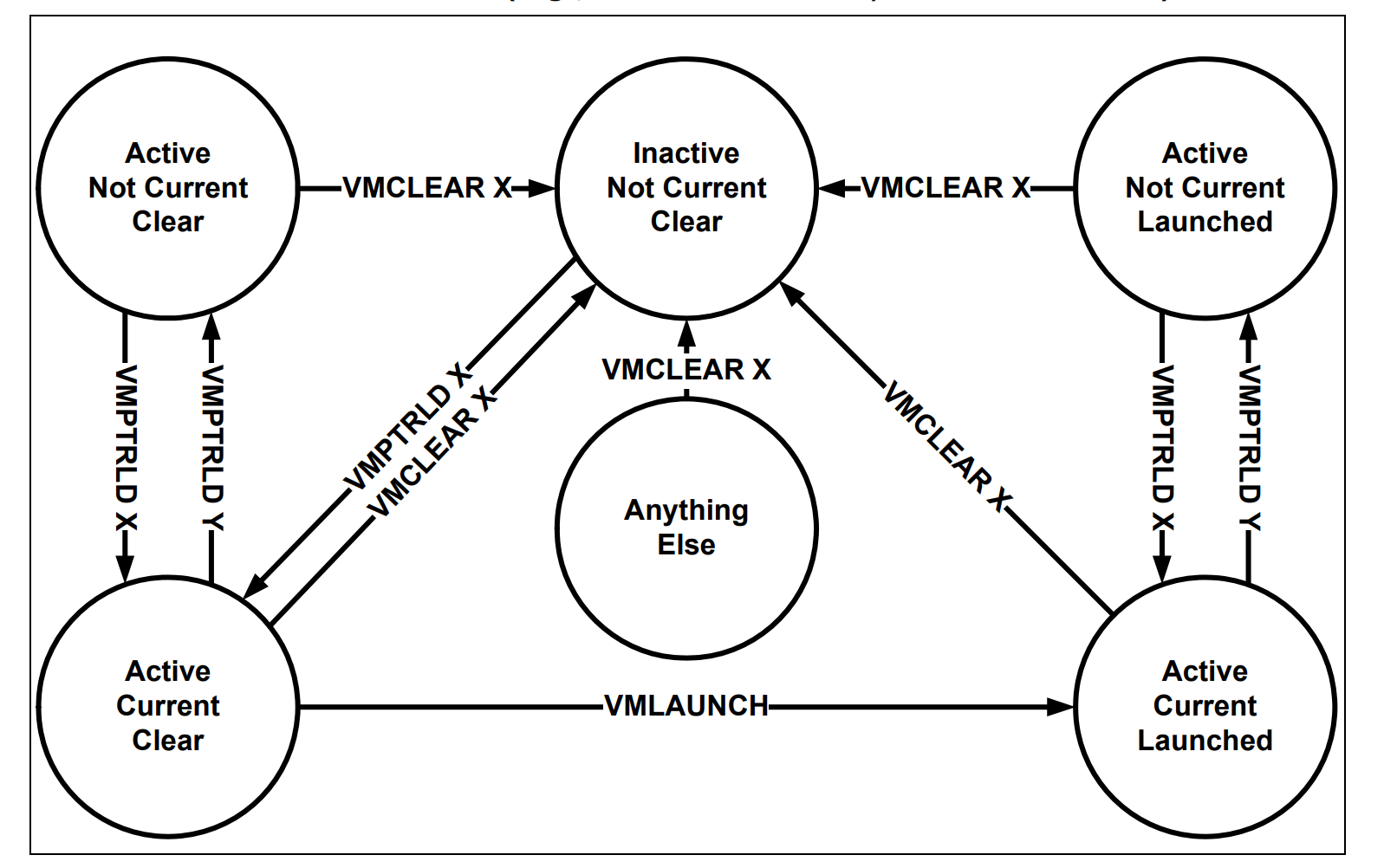
The above picture illustrates the lifecycle of VMX operation in the VMCS Region.
Initializing VMCS Region
A VMM should use different VMCS Regions, so we need to set logical processor affinity and run our initialization routine multiple times.
The location where the VMCS located is called the “VMCS Region”.
VMCS Region is a
- 4 Kbyte (bits 11:0 must be zero)
- Must be aligned to the 4KB boundary
This pointer must not set bits beyond the processor’s physical-address width (we can determine a processor’s physical-address width by executing CPUID with 80000008H in EAX. The physical-address width is returned in bits 7:0 of EAX.)
There might be several VMCSs simultaneously in a processor, but just one of them is currently active, and the VMLAUNCH, VMREAD, VMRESUME, and VMWRITE instructions operate only on the current VMCS.
Using VMPTRLD sets the current VMCS on a logical processor.
The memory operand of the VMCLEAR instruction is also the address of a VMCS. After executing the instruction, VMCS is neither active nor current on the logical processor. If the VMCS had been current on the logical processor, the logical processor no longer has a current VMCS.
VMPTRST is responsible to give the current VMCS pointer it stores the value FFFFFFFFFFFFFFFFH if there is no current VMCS.
The launching state of a VMCS determines which VM-entry instruction should be used with that VMCS. The VMLAUNCH instruction requires a VMCS whose launch state is “clear”; the VMRESUME instruction requires a VMCS whose launch state is “launched”. A logical processor maintains a VMCS’s launch state in the corresponding VMCS region.
If the launch state of the current VMCS is “clear”, successful execution of the VMLAUNCH instruction changes the launch state to “launched”.
The memory operand of the VMCLEAR instruction is the address of a VMCS. After execution of the instruction, the launch state of that VMCS is “clear”.
There are no other ways to modify the launch state of a VMCS (it cannot be modified using VMWRITE), and there is no direct way to discover it (it cannot be read using VMREAD).
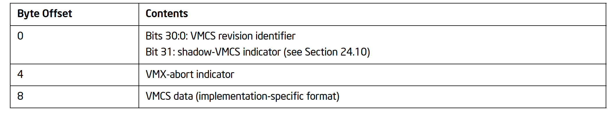
The following picture illustrates the contents of a VMCS Region.
The following code is responsible for allocating VMCS Region :
1
2
3
4
5
6
7
8
9
10
11
12
13
14
15
16
17
18
19
20
21
22
23
24
25
26
27
28
29
30
31
32
33
34
35
36
37
38
39
40
41
42
43
44
45
46
47
48
49
50
51
52
53
54
55
56
57
58
BOOLEAN
AllocateVmcsRegion(IN VIRTUAL_MACHINE_STATE * GuestState)
{
    //
    // at IRQL > DISPATCH_LEVEL memory allocation routines don't work
    //
    if (KeGetCurrentIrql() > DISPATCH_LEVEL)
        KeRaiseIrqlToDpcLevel();

    PHYSICAL_ADDRESS PhysicalMax = {0};
    PhysicalMax.QuadPart         = MAXULONG64;

    int    VMCSSize = 2 * VMCS_SIZE;
    BYTE * Buffer   = MmAllocateContiguousMemory(VMCSSize + ALIGNMENT_PAGE_SIZE, PhysicalMax); // Allocating a 4-KByte Contigous Memory region

    PHYSICAL_ADDRESS Highest = {0}, Lowest = {0};
    Highest.QuadPart = ~0;

    // BYTE* Buffer = MmAllocateContiguousMemorySpecifyCache(VMXONSize + ALIGNMENT_PAGE_SIZE, Lowest, Highest, Lowest, MmNonCached);

    UINT64 PhysicalBuffer = VirtualToPhysicalAddress(Buffer);
    if (Buffer == NULL)
    {
        DbgPrint("[*] Error : Couldn't Allocate Buffer for VMCS Region.");
        return FALSE; // ntStatus = STATUS_INSUFFICIENT_RESOURCES;
    }
    // zero-out memory
    RtlSecureZeroMemory(Buffer, VMCSSize + ALIGNMENT_PAGE_SIZE);
    UINT64 AlignedPhysicalBuffer = (BYTE *)((ULONG_PTR)(PhysicalBuffer + ALIGNMENT_PAGE_SIZE - 1) & ~(ALIGNMENT_PAGE_SIZE - 1));

    UINT64 AlignedVirtualBuffer = (BYTE *)((ULONG_PTR)(Buffer + ALIGNMENT_PAGE_SIZE - 1) & ~(ALIGNMENT_PAGE_SIZE - 1));

    DbgPrint("[*] Virtual allocated buffer for VMCS at %llx", Buffer);
    DbgPrint("[*] Virtual aligned allocated buffer for VMCS at %llx", AlignedVirtualBuffer);
    DbgPrint("[*] Aligned physical buffer allocated for VMCS at %llx", AlignedPhysicalBuffer);

    // get IA32_VMX_BASIC_MSR RevisionId

    IA32_VMX_BASIC_MSR basic = {0};

    basic.All = __readmsr(MSR_IA32_VMX_BASIC);

    DbgPrint("[*] MSR_IA32_VMX_BASIC (MSR 0x480) Revision Identifier %llx", basic.Fields.RevisionIdentifier);

    // Changing Revision Identifier
    *(UINT64 *)AlignedVirtualBuffer = basic.Fields.RevisionIdentifier;

    int Status = __vmx_vmptrld(&AlignedPhysicalBuffer);
    if (Status)
    {
        DbgPrint("[*] VMCS failed with status %d\n", Status);
        return FALSE;
    }

    g_GuestState->VmcsRegion = AlignedPhysicalBuffer;

    return TRUE;
}
The above code is exactly the same as VMXON Region except for __vmx_vmptrld instead of __vmx_on, __vmx_vmptrld is the intrinsic function for VMPTRLD instruction.
In VMCS, we should find the Revision Identifier from MSR_IA32_VMX_BASIC and write it in VMCS Region before executing VMPTRLD.
The MSR_IA32_VMX_BASIC is defined as below.
1
2
3
4
5
6
7
8
9
10
11
12
13
14
15
16
17
18
typedef union _IA32_VMX_BASIC_MSR
{
    ULONG64 All;
    struct
    {
        ULONG32 RevisionIdentifier : 31;   // [0-30]
        ULONG32 Reserved1 : 1;             // [31]
        ULONG32 RegionSize : 12;           // [32-43]
        ULONG32 RegionClear : 1;           // [44]
        ULONG32 Reserved2 : 3;             // [45-47]
        ULONG32 SupportedIA64 : 1;         // [48]
        ULONG32 SupportedDualMoniter : 1;  // [49]
        ULONG32 MemoryType : 4;            // [50-53]
        ULONG32 VmExitReport : 1;          // [54]
        ULONG32 VmxCapabilityHint : 1;     // [55]
        ULONG32 Reserved3 : 8;             // [56-63]
    } Fields;
} IA32_VMX_BASIC_MSR, *PIA32_VMX_BASIC_MSR;
VMXOFF Instruction
After configuring the above regions, now it’s time to think about DrvClose when the user-mode application no longer maintains the handle to the driver. At this time, we should terminate VMX and free every memory that we allocated before.
The following function is responsible for executing VMXOFF and then calling MmFreeContiguousMemory to free the allocated memory :
1
2
3
4
5
6
7
8
9
10
11
12
13
14
15
16
17
18
19
VOID
TerminateVmx()
{
    DbgPrint("\n[*] Terminating VMX...\n");

    KAFFINITY AffinityMask;
    for (size_t i = 0; i < ProcessorCounts; i++)
    {
        AffinityMask = MathPower(2, i);
        KeSetSystemAffinityThread(AffinityMask);
        DbgPrint("\t\tCurrent thread is executing in %d th logical processor.", i);

        __vmx_off();
        MmFreeContiguousMemory(PhysicalToVirtualAddress(g_GuestState[i].VmxonRegion));
        MmFreeContiguousMemory(PhysicalToVirtualAddress(g_GuestState[i].VmcsRegion));
    }

    DbgPrint("[*] VMX Operation turned off successfully. \n");
}
Remember to convert VMXON and VMCS Regions to virtual addresses because MmFreeContiguousMemory accepts virtual addresses; otherwise, it leads to a BSOD.
Ok, It’s almost done!
Testing VMM

Let’s create a test case for our code, first a function for initiating VMXON and VMCS Regions through all logical processors.
1
2
3
4
5
6
7
8
9
10
11
12
13
14
15
16
17
18
19
20
21
22
23
24
25
26
27
28
29
30
31
32
33
34
35
36
37
38
39
40
41
42
43
44
45
46
VIRTUAL_MACHINE_STATE * g_GuestState;
int                     ProcessorCounts;

BOOLEAN
InitializeVmx()
{
    if (!IsVmxSupported())
    {
        DbgPrint("[*] VMX is not supported in this machine !");
        return FALSE;
    }

    ProcessorCounts = KeQueryActiveProcessorCount(0);
    g_GuestState    = ExAllocatePoolWithTag(NonPagedPool,
                                         sizeof(VIRTUAL_MACHINE_STATE) * ProcessorCounts,
                                         POOLTAG);

    DbgPrint("\n=====================================================\n");

    KAFFINITY AffinityMask;
    for (size_t i = 0; i < ProcessorCounts; i++)
    {
        AffinityMask = MathPower(2, i);

        KeSetSystemAffinityThread(AffinityMask);

        DbgPrint("\t\tCurrent thread is executing in %d th logical processor.", i);

        //
        // Enabling VMX Operation
        //
        AsmEnableVmxOperation();

        DbgPrint("[*] VMX Operation Enabled Successfully !");

        AllocateVmxonRegion(&g_GuestState[i]);
        AllocateVmcsRegion(&g_GuestState[i]);

        DbgPrint("[*] VMCS Region is allocated at  ===============> %llx", g_GuestState[i].VmcsRegion);
        DbgPrint("[*] VMXON Region is allocated at ===============> %llx", g_GuestState[i].VmxonRegion);

        DbgPrint("\n=====================================================\n");
    }

    return TRUE;
}
The above function should be called from IRP MJ CREATE, so let’s modify our DrvCreate to :
1
2
3
4
5
6
7
8
9
10
11
12
13
14
15
NTSTATUS DrvCreate(IN PDEVICE_OBJECT DeviceObject, IN PIRP Irp)
{

    DbgPrint("[*] DrvCreate Called !");

    if (InitializeVmx()) {
        DbgPrint("[*] VMX Initiated Successfully.");
    }

    Irp->IoStatus.Status = STATUS_SUCCESS;
    Irp->IoStatus.Information = 0;
    IoCompleteRequest(Irp, IO_NO_INCREMENT);

    return STATUS_SUCCESS;
}
And modify DrvClose to :
1
2
3
4
5
6
7
8
9
10
11
12
13
14
15
16
NTSTATUS
DrvClose(IN PDEVICE_OBJECT DeviceObject, IN PIRP Irp)
{
    DbgPrint("[*] DrvClose Called !");

    //
    // executing VMXOFF on every logical processor
    //
    TerminateVmx();

    Irp->IoStatus.Status      = STATUS_SUCCESS;
    Irp->IoStatus.Information = 0;
    IoCompleteRequest(Irp, IO_NO_INCREMENT);

    return STATUS_SUCCESS;
}
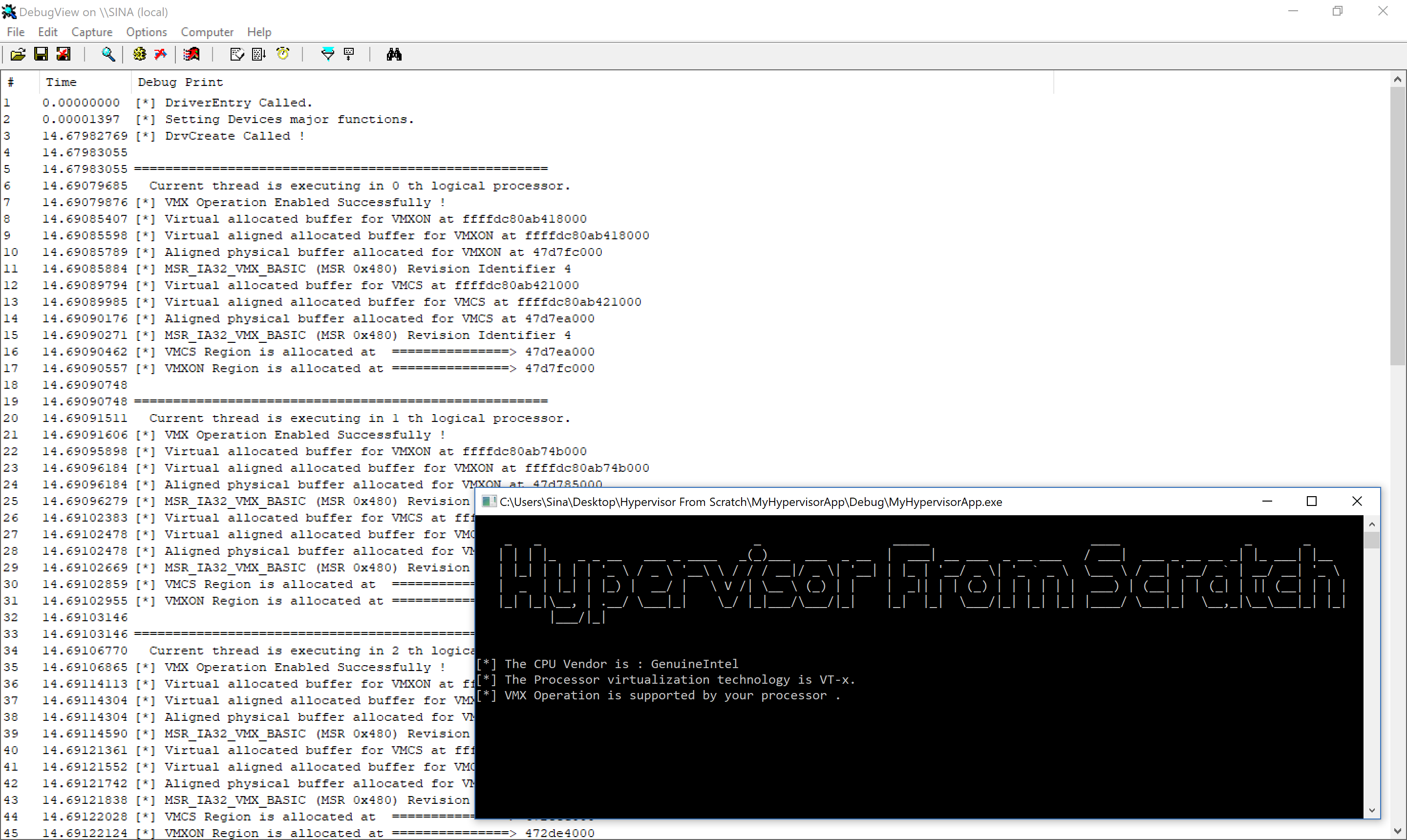
Now, run the code. In the case of creating the handle (You can see that our regions were allocated successfully).
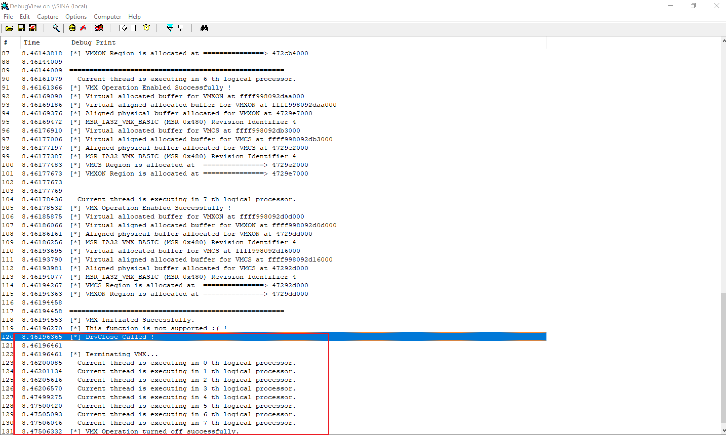
And when we call CloseHandle from user mode:
Conclusion
In this part, we learned about different types of IOCTL Dispatching. We saw different functions in Windows to manage our VMM, and we initialized the VMXON Regions and VMCS Regions, then terminated them.
In the future, we’ll focus on Exteneded Page Table (EPT), VMCS, and different actions that can be performed in VMCS Regions to control our guest software.
The fourth part is also available [here].(https://rayanfam.com/topics/hypervisor-from-scratch-part-4/).
Note: Remember that hypervisors change over time because new features are added to the operating systems or new technologies are used. For example, updates to Meltdown & Spectre have made a lot of changes to the hypervisors. So, if you want to use Hypervisor From Scratch in your projects, research, or whatever, you should use the HyperDbg drivers. HyperDbg is actively maintained, stable, and reliable, ensuring you avoid the errors and instability problems that can arise from using older parts of the tutorial series.
References
[1] Intel® 64 and IA-32 architectures software developer’s manual combined volumes 3 (https://software.intel.com/en-us/articles/intel-sdm)
[2] Windows Driver Samples (https://github.com/Microsoft/Windows-driver-samples)
[3] Driver Development Part 2: Introduction to Implementing IOCTLs (https://www.codeproject.com/Articles/9575/Driver-Development-Part-2-Introduction-to-Implemen)
[3] Hyperplatform (https://github.com/tandasat/HyperPlatform)
[4] PAGED_CODE macro (https://technet.microsoft.com/en-us/ff558773(v=vs.96))
[5] HVPP (https://github.com/wbenny/hvpp)
[6] HyperBone Project (https://github.com/DarthTon/HyperBone)
[7] Memory Caching Types (https://docs.microsoft.com/en-us/windows-hardware/drivers/ddi/content/wdm/ne-wdm-_memory_caching_type)
[8] What is writeback cache? (https://whatis.techtarget.com/definition/write-back)
[9] Buffer Descriptions for I/O Control Codes (https://docs.microsoft.com/en-us/windows-hardware/drivers/kernel/buffer-descriptions-for-i-o-control-codes)
[10] Defining I/O Control Codes (https://docs.microsoft.com/en-us/windows-hardware/drivers/kernel/defining-i-o-control-codes)
Comments powered by Disqus.